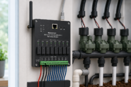
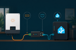
I’ve been slowly building out a smart garden irrigation system, and the piece that ties everything together is the central controller. This is the box that decides which valve opens, when the pump runs, and how all of that talks to Home Assistant. In this post I want to walk through how I’m designing it, the relay hub, the microcontroller running the logic, and the slightly fiddly business of running two different voltage rails through the same enclosure.
The Junction Box
Although all electronics and water valves will be in a wooden cabinet and therefore not directly exposed to the outdoor weather, I prefer to have the electronics in a waterproof box.
Since we’re also dealing with different voltages, I’d like to have them all in one place.
What equipment will be in this junction box?
- 6x 230V sockets
- Waveshare 8CH relay controller
- 24VAC transformer, however not with a 230V plug on it, but just wires. I got this 2A transformer from my irrigation setup 10 years ago. It’s still working :). This will be used to power the Rainbird valves.
- 24VDC transformer with 230V plug to power the Autosen waterflow device
- One or two PVC boxes to hold wires.
I’ve found a waterproof junction box on Amazon, from brand LeMotech and it has a transparent cover. On one side two hinges, on the other side two clips to close it firmly.
The box size I’m using is 400x300x180mm
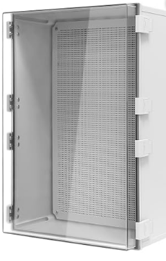
There is a rubber seal between the box and the lid. It comes with 2 or 3 waterproof cable glands, however, there are no pre-drilled holes or push-through options. I purchased a separate “step drill bit” to drill the holes the right size, accurately.

Within the box there is a mounting plate, mounted with 4 screws to the junction box.

Anticipating that not everything I’d mount would line up with the holes on this plate, I replaced it with a thin piece of wood instead. It’s more steady, it gives me more flexibility and it has the same thickness as the original mounting plate.

230V sockets
Not spectacular, but as mentioned earlier, I’d like to have six 230V sockets available. Two of them will be wired to the Waveshare relays (bottom row), so I can power cycle them when necessary.
The other four will have constant 230V on them.

The hub: a Waveshare 8CH WiFi relay controller
At the center of the box sits a Waveshare 8-channel WiFi relay controller. I picked this over building my own relay board from scratch because it already gives me eight isolated relay outputs, a stable WiFi module, and enough headroom to control not just my five Rainbird solenoid valves but also the pump and a couple of switched 230V outlets in the same enclosure. Rather than treat it as a standalone smart-home gadget, I’m flashing it so it plays nicely with ESPHome, which lets Home Assistant see and control every relay channel directly.
The ESPHome yaml is shared in the dedicated post for this device: https://rutg3r.com/install-esphome-waveshare-esp32-s3-relay-module/
 Zoomed in on the relays, the two 230V sockets will be switched via the Waveshare on relay 7 and 8. The wire color is brown here, but it’s changed later to black, which makes more sense since these are the switching wires. The initial phase (L) is not connected here yet.
Each relay terminal block has 3 wire connectors:
- Left = NO (Normally Open)
- Middle = COM
- Right = NC (Normally Closed)
I prefer that the relays are off when not in use, so the brown black wire will be connected to the left screw connector. The middle one will be the phase (L). The right one will not be used in my setup.
The available space was becoming tight. Maybe next time I’ll go with a bigger junction box. Anyway, the final result:

Another set of brains: Two times a M5Stack ATOM S3 Lite
Sitting alongside the relay board are two M5Stack ATOM S3 Lite units, also running ESPHome. Its job isn’t to switch anything, that’s the relay board’s job, it’s to read the sensors: the Autosen Vortex flow and temperature meter on the main line, and eventually feed data back for leak detection. Splitting ‘sensing’ and ‘switching’ across two separate ESPHome nodes rather than cramming everything onto one board keeps the wiring simpler and means I can swap or debug one half without touching the other.
The setup including yamls are explained here: https://rutg3r.com/dual-4-20-ma-loops-with-esphome-reading-water-flow-and-temperature-from-an-autosen-as010/
Two power rails, one enclosure
The part that took the most thought was power. The Rainbird solenoid valves are 24VAC devices, that’s the industry standard for irrigation valves, and it’s what the valve manifold expects. But the ATOM S3, the Waveshare relay board, and the Autosen device all want clean 24VDC or 5V, not AC. So the enclosure ends up with two separate supplies: a 24VAC transformer feeding the valve manifold through the relay outputs, and a separate 24VDC supply, stepped down further to 5V where needed, feeding the microcontrollers and relay coils. I’m keeping the AC and DC sides physically separated and clearly labeling every terminal block, because mixing those up even once would let out the magic smoke.
What’s next
Next, I’ll build a wooden cabinet to house this junction box, the manifold with the Rainbird valves, and the groundwater pump.